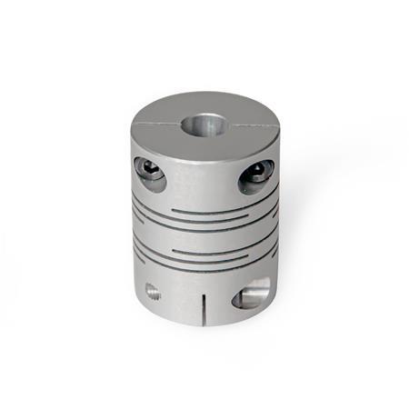
B | Without keyway |
d1 | d2 - d3 H8 recommended shaft tolerance h7 | |||||
---|---|---|---|---|---|---|
12 | 4-4 | 4-5 | 5-5 | - | - | - |
16 | 5-5 | 5-6 | 6-6 | - | - | - |
20 | 5-5 | 5-6 | 5-8 | 6-6 | 6-8 | 8-8 |
25 | 6-6 | 6-8 | 6-10 | 8-8 | 8-10 | 10-10 |
32 | 10-10 | 10-12 | 12-12 | - | - | - |
d1 | d4 | l1 | l2 recommended shaft insertion depth | l3 | l4 | Tightening torque of the screw in Nm ≈ |
---|---|---|---|---|---|---|
12 | M 2 | 18,5 | 5 | 2,5 | 4 | 0.5 |
16 | M 2,5 | 23 | 6,5 | 3,25 | 5 | 1 |
20 | M 2,5 | 26 | 7,5 | 3,75 | 6,5 | 1 |
25 | M 3 | 31 | 8,5 | 4,25 | 9 | 1.5 |
32 | M 4 | 41 | 12 | 6 | 11 | 2.5 |
Show / Hide columns
Show / Hide columns
|
Like all mechanical parts, shafts are subjected to manufacturing and assembly tolerances that generally cannot be entirely eliminated even with extensive technical measures. |
|||||||||||
Error type |
Misalignment diagram |
||||||||||
Lateral |
|||||||||||
Angular |
|||||||||||
Axial |
|||||||||||
Runout |
For correct fastening of the coupling hubs, the shaft must be installed according to the recommended shaft insertion depth l2. The shaft insertion depth l2 is specified in the standard sheet of the respective coupling. |
The diagrams show the change in static torsional stiffness within the permissible operating temperature range, under the assumption that the static torsional stiffness at 20 °C is 100 percent. The torsional stiffness of the couplings decreases with increasing temperature. |
|||||||||||
When the shaft ends are installed in eccentric arrangements, the coupling constantly attempts to return to its neutral position. The resulting force is referred to as restoring force. |
|||||||||||
If the coupling is under pressure, subject to compressive load in the axial direction, it will strive to return to its neutral position. The force that counteracts the compressive force is referred to as restoring force. |
|||||||||||
Our service team is available from Monday to Friday between 7:00 AM and 5:30 PM: +49 7723 6507 - 0