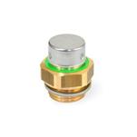
 ELESA original design
 code: SFN. / SFP. / SFP+a
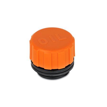
Type: A - Without dipstick
Standard sheet GN 552
Print this page
Application video Breather caps
Description of function
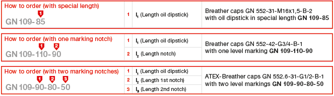
Level markings / Special lengths GN 109
Plastic Characteristics
Product description
Function and operational criteria of breather caps GN 552 see description of function.
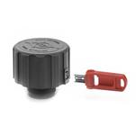
MAX-MIN markings can easily be added to the flats of a dipstick (see GN 109).
Type with dipstick (Type B) is only available for marks 0, 1 and 2 as follows:
Size 31 - all threads
Size 42 - G 3/4 and 1 only
Size 57 - G 1 1/4 and G 1 1/2 only
Specification
Plastic
- Temperature resistant up to 100 °C
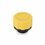
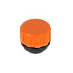
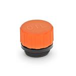
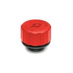
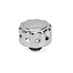
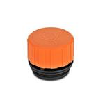
- Upper part (cap)
Orange, RAL 2004 - Lower part (threaded part)
Black
Seal
Rubber NBR (Perbunan®)
Air filter wire mesh
- Zinc plated
- Filtration 50 to 60 µm
Air filter PU-foam (Polyurethane)
- Filtration 40 µm
- Temperature resistant up to 100 °C
Dipstick
Steel, phosphated
RoHS
On request
Fluid level markings / special lengths
see GN 109