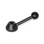
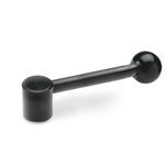
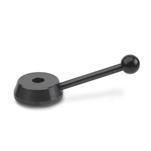
B | Without keyway |
K | With keyway |
V | With square |
M | Cover with indicator point |
N | Cover plain |
d1 | d2 Bore H7 Square H11 | d3 | d4 | d5 | d6 | h1 | h2 | h3 | h4 ≈ | Length l | |
---|---|---|---|---|---|---|---|---|---|---|---|
32 | 10 | - | 25 | 23 | 18 | 8 | 21 | 15 | 4,2 | 43 | 84 |
40 | 10 | 12 | 32 | 30 | 21 | 9 | 25 | 19 | 4 | 54 | 106 |
50 | 14 | 16 | 40 | 37,5 | 23 | 11 | 28 | 22 | 3,8 | 63 | 130 |
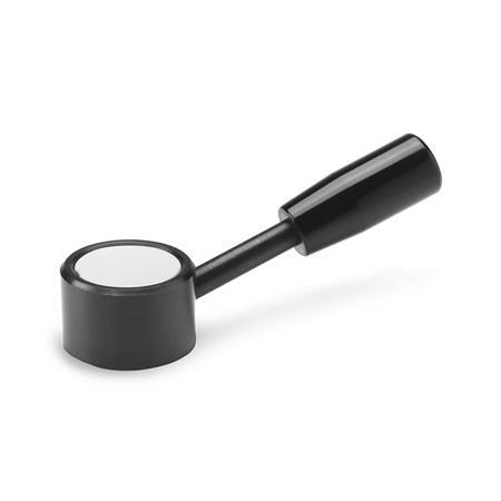
GN 750 control levers with Spring Plungers GN 614 (spring plunger GN 614) mounted with a cross pin. The arrangement of the spring plunger facilitates simple installation; if desired the detent cone can be drilled out from the shifting hub in situ before the plunger is fitted. The recessed shaft and the bore for the spring plunger are hidden by the cover. |
|||||||||||
Control lever GN 750 with hub keyway / parallel key, mounted axially by Countersunk Washers GN 184, with an annular groove for attaching pins to limit the angle of rotation. |
Show / Hide columns
|
|||||||||||||||||||||||||||||||||||||||||||||||||||||||||||||||||||||||||||||||||||||||||
The connection between the operating element and the shaft consists very often of a cross pin or a grub screw. The cross hole GN 110 is to be ordered as a separate item in shopping cart step 1 under note. |
|||||||||||||||||||||||||||||||||||||||||||||||||||||||||||||||||||||||||||||||||||||||||
Our service team is available from Monday to Friday between 7:30 AM and 5:00 PM: +49 7723 6507 - 0