d1 | d2 | h1 | h2 | h3 | h4 | k1 | k2 | k3 | k4 | k5 | l1 | l2 | r | sw1 | sw2 | Couple de serrage en Nm | Charge nominale en t (WLL) |
---|---|---|---|---|---|---|---|---|---|---|---|---|---|---|---|---|---|
M 8 | 24 | 87 | 75 | 40 | 35 | 12 | 52 | 34 | 75 | 45 | 11 | 30 | 32 | 13 | 5 | 30 | 0.63 |
M 10 | 24 | 87 | 75 | 39 | 36 | 12 | 52 | 34 | 75 | 45 | 15 | 30 | 32 | 17 | 6 | 60 | 0.9 |
M 12 | 26 | 87 | 75 | 38 | 37 | 12 | 52 | 34 | 75 | 45 | 18 | 32 | 32 | 19 | 8 | 150 | 1.35 |
M 16 | 30 | 99 | 85 | 39 | 46 | 13,5 | 56 | 38 | 86 | 47 | 22 | 34,5 | 38 | 24 | 10 | 150 | 2 |
M 20 | 45 | 127 | 110 | 55 | 55 | 16,5 | 82 | 54 | 113 | 64 | 32 | 50 | 48 | 30 | 12 | 400 | 3.5 |
M 24 | 45 | 143 | 125 | 67 | 58 | 18 | 82 | 54 | 130 | 78 | 37 | 50 | 48 | 36 | 14 | 760 | 4.5 |
M 30 | 60 | 170 | 147 | 67 | 80 | 22,5 | 103 | 65 | 151 | 80 | 49 | 60 | 67 | 46 | 17 | 1000 | 6.7 |
Méthode de montage |
|||||||||||
Nombre |
1 |
1 |
2 |
2 |
2 |
2 |
2 |
3 et 4 |
3 et 4 |
3 et 4 |
|
Angle |
0° à 7° |
90° |
0° |
90° |
0° à 45° |
45 à 60° |
asymm. |
0° |
45 à 60° |
asymm. |
|
Facteur |
1 |
1 |
2 |
2 |
1,4 |
1 |
1 |
2,1 |
1,5 |
1 |
|
M 8 |
0,63 t |
0,63 t |
1.26 t |
1.26 t |
0.88 t |
0.63 t |
0.63 t |
1.32 t |
0.95 t |
0.63 t |
|
M 10 |
0.90 t |
0.90 t |
1.80 t |
1.80 t |
1.30 t |
0.90 t |
0.90 t |
1.90 t |
1.35 t |
0.90 t |
|
M 12 |
1.35 t |
1.35 t |
2.70 t |
2.70 t |
1.90 t |
1.35 t |
1.35 t |
2.84 t |
2.00 t |
1.35 t |
|
M 16 |
2.00 t |
2.00 t |
4.00 t |
4.00 t |
2.80 t |
2.00 t |
2.00 t |
4.25 t |
3.00 t |
2.00 t |
|
M 20 |
3.50 t |
3.50 t |
7.00 t |
7.00 t |
4.90 t |
3.50 t |
3.50 t |
7.35 t |
5.25 t |
3.50 t |
|
M 24 |
4.50 t |
4.50 t |
9.00 t |
9.00 t |
6.30 t |
4.50 t |
4.50 t |
9.50 t |
6.75 t |
4.50 t |
|
M 30 |
6.70 t |
6.70 t |
13.40 t |
13.40 t |
9.50 t |
6.70 t |
6.70 t |
14.10 t |
10.00 t |
6.70 t |
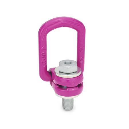
The load capacity table shows the maximum loads in metric tons in relation to the mounting method at an operating temperature of -40 °C to +100 °C. The nominal load capacity refers to the most disadvantageous loading conditions, whereby a safety factor of 4 is taken into account for all values. The rotating load ring GN 586.1 may only be used if it is screwed on in accordance with the minimum screw-in length and set in the tension direction. The screw-on surface has to be plane and at a right angle to the threaded hole. When firmly mounted, the load ring must rotate freely by 360° and must not rest on edges or other lifting gear, e.g. on crane hooks. Rotating load rings are not suitable for permanent rotary movements under load. The operating instruction contains further guidelines and is included with every load ring (see also at www.ganternorm.com/en/service). |
Nuestro equipo de servicio está disponible de lunes a viernes, entre las 7:00 AM – 5:30 PM : +49 7723 6507-0