Product description
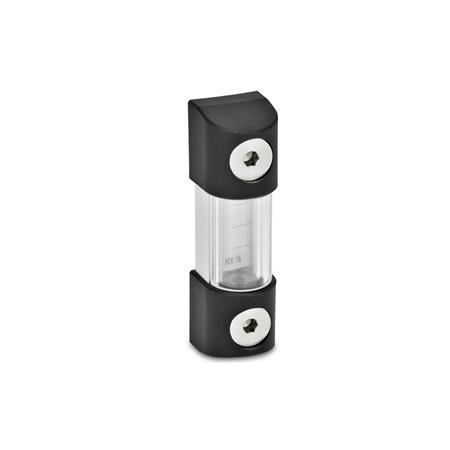
Owing to the U-rail and the cover, oil level indicators GN 654.1 are extremely stable and are therefore suitable for great lengths. The fluid level can also be viewed from the side.
Oil level indicators GN 654.1 have a high chemical resistance and are also suitable for media containing or based on glycol.
For special requirements in terms of chemical resistance, pressure and temperature resistance, please contact us.
Specification
Glass tube
Borosilicate glass (Pyrex®)
- Temperature resistant up to 130 °C
- Highest mechanical and thermal resistance
O-ring
Rubber FKM (Viton®)
Set screw
Stainless steel AISI 303
U-rail
Aluminum
Anodized, natural color
End pieces
Technopolymer (Polyamide PA)
- Black, matte finish
- Temperature resistant up to 130 °C
Cover
Plastic, chrystal-clear Polycarbonate (PC)
RoHS
On request
Other lengths l1
With temperatue display
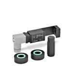
With electrical temperature monitoring


