Product description
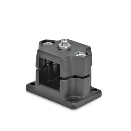
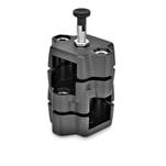
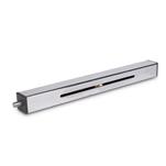
With flanged locking slide units GN 147.7, recurring positions along a square construction tube can be moved to easily and quickly. The required holes for type R or countersinks for type D can be created by the user according to the design instructions or ordered as completely finished construction tubes with locking holes GN 990.1.
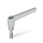
For quick clamping without tools, the socket cap screws at the screw locations z, can be replaced by the adjustable hand levers GN 911 listed in the table as accessories. Centering bushings in the pass-through holes eliminate the axial play between the top and bottom parts of the locking slide units.
Flanged locking slide units GN 147.7 are delivered with unmounted indexing plunger (type R) or spring plunger (type D). Type G with thread is universally suitable for specific applications.
Specification
Locking slide units
Aluminum
Powder coated
Black, RAL 9005, textured finishSW
Fastening elements / transfer elements
- Socket cap screws DIN 912
- Hex nuts DIN 985
- Centering bushings
Stainless steel AISI 304
Indexing plunger GN 717, type CK
- Plunger pin
Stainless steel AISI 303 - Knob
Plastic, Polyamide (PA)
Black, matte finish
Spring plunger GN 615.9, type KN
- Stainless Steel AISI 303
- Ball with friction bearing
- With internal hex
- Stainless steel lock nut ISO 4035
RoHS

