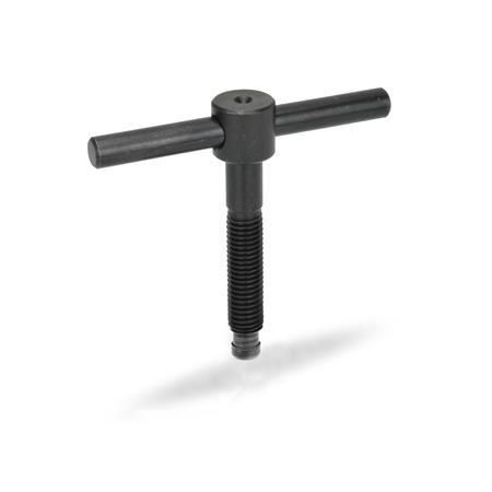
E | Without thrust pad |
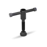
F | With thrust pad DIN 6311 |
d1 | l1 | d2 | d3 | d4 h11 | l2 | l3 | l4 | l5 ≈ | z ≈ | ||
---|---|---|---|---|---|---|---|---|---|---|---|
M 6 | 40 | 50 | - | 12 | 5 | 4,5 | 10 | 50 | 10 | 2,2 | 5,4 |
M 8 | 50 | 60 | - | 14 | 6 | 6 | 12 | 60 | 15 | 3 | 6,8 |
M 10 | 60 | 70 | - | 18 | 8 | 8 | 14 | 80 | 20 | 3,6 | 8,2 |
M 12 | 70 | 80 | - | 20 | 10 | 8 | 18 | 100 | 20 | 4,5 | 8,6 |
M 16 | 75 | 90 | 110 | 24 | 12 | 12 | 20 | 120 | 20 | 5,3 | 10,6 |
M 20 | 75 | 90 | 110 | 30 | 16 | 15,5 | 28 | 140 | 20 | 5,6 | 12,4 |
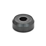
The thrust pad has to be held at an angle allowing the circlip to drop to the bottom of its groove with the split end downwards. The thrust point is then offered up to the split end of the circlip at the lowest possible angle and pressed home. |
|||||||||||
Our service team is available from Monday to Friday between 7:30 AM and 5:00 PM: +49 7723 6507 - 0