Product description
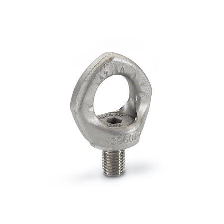
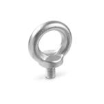
Lifting eye bolts GN 581.5 are mounted in rotating bearings, allowing the direction of the force action to be adjusted and preventing inadvertent loosening or overturning (as potentially possible in lifting eye bolts DIN 580).
Lifting eye bolts GN 581.5 offer a high load carrying capacity and they are tested to meet safety standards (safety factor 4).
The rated load carrying capacity listed in the above table is clearly marked on the ring. It applies to the most unfavourable load application of the load types listed opposite.
Lifting eye bolts GN 581.5 eye bolts comply with Mechanical Engineering Directive 2006 / 42 / EG and are BG tested.
The integrated RFID transponder clearly marks and identifies the lifting point, e.g. during the prescribed regular inspection.
The hex socket bolt cannot be removed from the ring.
Other important information and notes can also be found in the operating instruction. It is part of the scope of delivery and can be downloaded as a PDF at ganternorm.com/service/downloads/operating-instructions.
Specification
Ring
Stainless steel AISI 318LN
- Forged
- 100% electro magnetic tensile test to EN1677
- Plain
Bolt
Stainless steel AISI 318LN
RoHS

