Product description
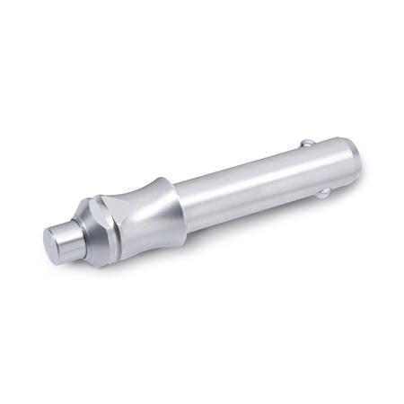
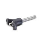
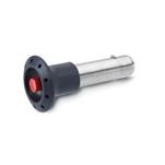
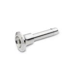
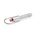
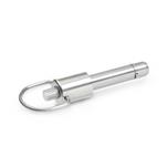
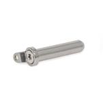
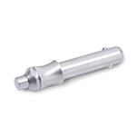
Ball lock pins GN 113.3 are used for quick fixing, connecting and locking of various parts and workpieces. A typical application is locating pins which have often to be removed and installed again.
By pressing the spring loaded push button both balls are unlocked and by releasing it the balls are locked again.
Ball lock pins GN 113.3 are renowned for their compactness. The eye ring is enclosed unmounted.
The technical appendix contains the load capacities for the double-sided shearing resistance (breaking strength).
Specification
Stainless steel AISI 303
Balls
Stainless steel AISI 420C
Pressure spring
Stainless steel AISI 631
Eye ring
Stainless steel AISI 301
Operating temperature up to 250 °C
RoHS
Accessory
Holding Bushings GN 1140
Ball Chains GN 111
Ball Chains GN 111.5 (Edelstahl)
Retaining Cables GN 111.2
Retaining Cables GN 111.2
Spiral Retaining Cables GN 111.4
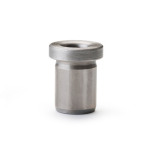
Guide Bushings DIN 172 (with collar)
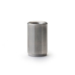
Guide Bushings DIN 179 (without collar)

