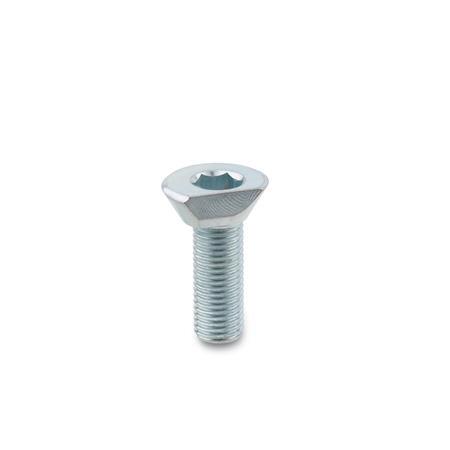
R | Clamping by clockwise rotation (d2 = right-hand thread) |
d1 Nominal dimension | d1 Actual dimension | d2 | Length l | h1 | h2 | r1 | r2 | s1 | s2 | A/F | x ±0,2 | z ±0,2 | Max. tightening torque in Nm | Max. clamping force F in kN |
---|---|---|---|---|---|---|---|---|---|---|---|---|---|---|
9 | 9,2 | M 4 | 8 | 3 | 3 | 4 | 4,6 | 1 | 0,6 | 2,5 | 3,5 | 4,2 | 1.5 | 0,09 |
12 | 11,7 | M 5 | 10 | 4 | 3,5 | 5 | 5,7 | 1,16 | 0,7 | 3 | 4,2 | 5,2 | 2 | 0,1 |
14 | 14,2 | M 6 | 12 | 5 | 4,5 | 6,1 | 7,1 | 1,44 | 1 | 4 | 5,4 | 6,4 | 5 | 0,3 |
18 | 18 | M 8 | 16 | 6 | 5,5 | 7,7 | 9 | 1,84 | 1,2 | 5 | 6,6 | 8 | 22 | 2,7 |
22 | 22,2 | M 10 | 20 | 7 | 6,5 | 9,4 | 11,1 | 2,16 | 1,7 | 6 | 8,3 | 9,8 | 35 | 4 |
26 | 25,8 | M 12 | 24 | 9 | 8 | 11,6 | 13,6 | 2,53 | 1,9 | 8 | 10,1 | 12 | 45 | 5,4 |
The head of the cam point screw has two cams: a radial clamping cam (with additional 30° taper) and an axial draw-down cam. Force components act on the clamping point which generate a draw-down effect and which, in addition to the friction, cause the workpiece to be pressed against a fixed stop. An additional draw-down effect is created by the thread and the 30° taper. |
•Position the thread bore(s) as specified •Screw the cam point screw in to the desired height and place it with its flat side facing the workpiece (note the minimum screw-in depth t) •For clamping effect above the head taper, the minimum clamping height should be h2 •A turn of approx. 135° is required for clamping |
Our service team is available from Monday to Friday between 7:30 AM and 5:00 PM: +49 7723 6507 - 0