Product description
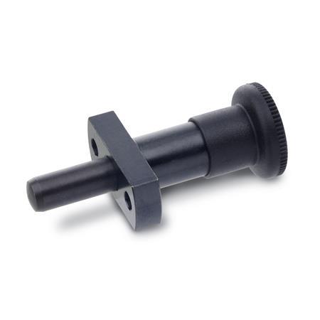
Indexing plungers GN 817.3, together with guide bushings DIN 172 / DIN 179, enable precise positioning.
The bushings are used to guide the plunger pin as well as for the indexing bore. The plunger pins and bushings are hardened and ground. Larger guide lengths further increase the precision.
Type C is used for such applications where the plunger has to stay in its retracted position. To achieve this, the knob is rotated by 90° degrees after being retracted. A notch keeps the plunger in this position.
Specification
Steel
- Blackened
- Plunger pin hardened and ground
Knob
Plastic (Polyamide PA)
- Black, matte finish
- Not removable
RoHS


