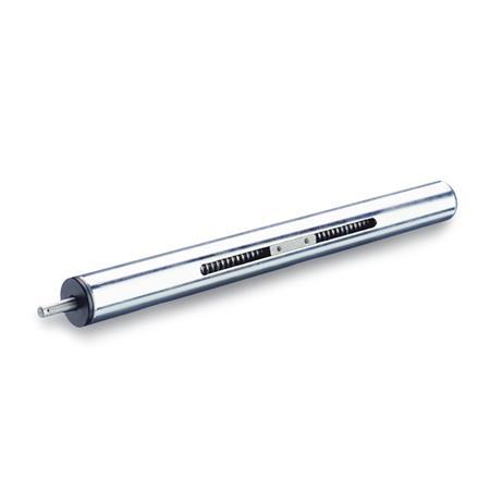
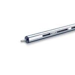
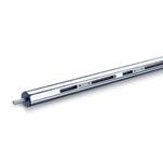
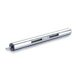
R1 | Right hand thread, shaft journal at one end |
R2* | Right hand thread, shaft journal at both ends |
L1 | Left hand thread, shaft journal at one end |
L2* | Left hand thread, shaft journal at both ends |
d1 | l1 Stroke (standard lengths) | max. stroke | Threaded spindle | d2 | d3 | l2 Total length | l3 | l4 | m1 | m2 | for parallel key DIN 6885 |
||||
---|---|---|---|---|---|---|---|---|---|---|---|---|---|---|---|
18 | 65 | 165 | 265 | - | - | 350 | TR10x3 | 6 | M 3 | l1+140 | 70 | 16 | 17 | 24 | A2x2x12 |
30 | 100 | 150 | 200 | 300 | - | 1250 | TR14x4 | 8 | M 4 | l1+205 | 102,5 | 16 | 23 | 38 | A2x2x12 |
40 | 70 | 170 | 220 | 270 | 320 | 1570 | TR20x4 | 12 | M 5 | l1+235 | 117,5 | 17 | 42 | 54 | A4x4x12 |
50 | 65 | 115 | 215 | 265 | 315 | 1565 | TR20x4 | 12 | M 6 | l1+240 | 120 | 18 | 42 | 54 | A4x4x12 |
60 | 220 | 720 | - | - | - | 1520 | TR24x5 | 14 | M 8 | l1+285 | 142,5 | 19 | 58 | 70 | A5x5x16 |
Show / Hide columns
Show / Hide columns
|
||||||||||||||||||||||||||||||||||||||||||||||||||||||||||||||||||||||||||||||||||||||||||||||||||||||||||||||||||||
The load data are applicable to linear actuators GN 291, GN 292, GN 293 made of steel (SCR) or stainless steel (NI). The specified forces Fy and Fz cause a flexure of the guide tube of approx. 0.5 mm. |
A lead nut moves in axial direction over the ball bearing trapezoidal thread spindle of the linear actuator. The follower ensures the anti-rotation and makes the link to the different linear actuator connectors. The linear actuators have been designed for manual operation (handwheel). The positioning accuracy is 0.2 mm / 300 mm stroke, the maximum reverse play is 0.1 mm. Guide tubes are available in chromed steel (SCR) or stainless steel (NI) non-rusting. They are made with the tolerance range of precision steel tubes DIN 2391 or DIN 2462. A wide variety of different components are available in the tube clamp connector program to fix the linear actuators in place and to upgrade these into linear actuator connectors. Also, digital position indicators (Position Indicators GN 953 / Position Indicators GN 954 / Position Indicators GN 9053 / Position Indicators GN 9054) may be attached to measure the displacement or the positioning. In applications where high torsion forces Mx occur, linear actuators with square tubing or double tube linear actuators should be given preference. A wide variety of different components from the tube clamp connector program is also available for the square tubings. The linear actuator connectors are composed of two-part elements, with the effect that the precision of the square tubes involves no special requirements. |
for Standard Stroke Lengths l1 of the Linear Actuators GN 291 |
||||||||||||||||||||||||||||||||||||||||||||||||||||||||||||||||||||||||||||||||||||||||||||||||||||||||||||||||||||
Show / Hide columns
|
||||||||||||||||||||||||||||||||||||||||||||||||||||||||||||||||||||||||||||||||||||||||||||||||||||||||||||||||||||
Specification Scale engraved with laser precision |
||||||||||||||||||||||||||||||||||||||||||||||||||||||||||||||||||||||||||||||||||||||||||||||||||||||||||||||||||||
Information Longitudinal scales can only be ordered togehter with linear actuators. |
||||||||||||||||||||||||||||||||||||||||||||||||||||||||||||||||||||||||||||||||||||||||||||||||||||||||||||||||||||
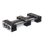
Two parallel sliding linear actuators GN 291 are connected with a transfer unit GN 391. |
|||||||||||
Two flanged linear actuator connectors GN 146.1 are moved parallel. For this two linear actuators GN 291 are connected with a transfer unit GN 391. The T- and angular gear GN 298-T/-W including the bevel gear wheels GN 297 and another transfer unit GN 391 connect the handwheel with the system. The handwheel is placed in a parallel position to the moving axes. |
Our service team is available from Monday to Friday between 7:30 AM and 5:00 PM: +49 7723 6507 - 0