Product description
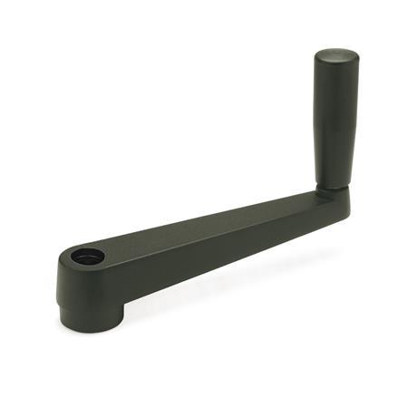
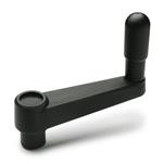
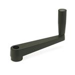
Cranked handles GN 471.1 are used for making adjustments or driving mechanisms.
The crank movement is transmitted via the revolving cylindrical handle. The revolving handle body can be held firmly and securely while cranking.
Cranked handles can also be ordered with cross holes GN 110.
Specification
Body
Zinc die casting
- Powder coated
black, textured finish - Contact face of hub machined
Revolving handle GN 598
Plastic, Polypropylen (PP)
- Black, matte finish
- Spindle steel
Zinc plated, blue passivated
RoHS

