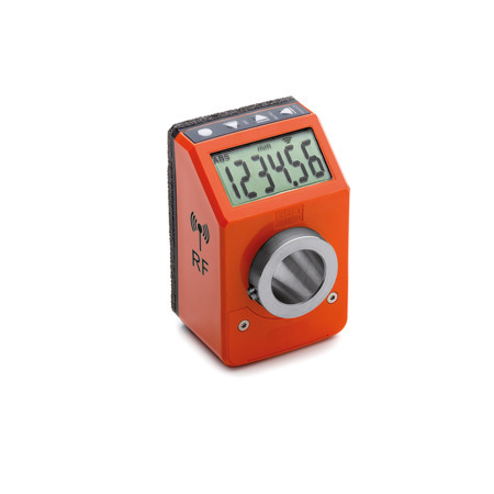
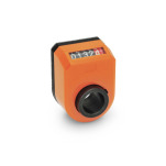
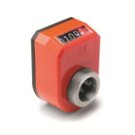
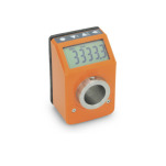
1 | Protection class IP 65 |
2 | Protection class IP 67 |
Tension feed |
Lithium battery CR2477, 3 V |
||||||||||
Battery life |
3 years |
||||||||||
Display |
6-digit LCD display, |
||||||||||
Reading scale |
-199999; 999999 |
||||||||||
Number of decimal digits |
programmable |
||||||||||
Units of measure |
mm, inch or degrees |
||||||||||
Rotation max. speed |
300 / 600 / 1000 U/min |
||||||||||
Precision |
10,000 impulses / revolution |
||||||||||
Working temperature |
0 °C ... 50 °C |
||||||||||
Humidity |
max. 95 % at 25 °C |
||||||||||
Interference protection |
acc. to guideline 2014/53/EU (RED) |
One advantage of electronic position determination lies in the wide range of display options on the position indicator. The following settings can be configured with the 3 / 4 function buttons:
The installed lithium battery has a life of over 3 years. Time to replace the battery is indicated by a symbol on the display. Battery replacement is easy - simply remove the front cover. |
The following components are required to start up the wireless system:
Each control unit can be coupled to up to 36 position indicators. A RJ45 network cable is used to connect to the machine control. The following standard bus systems are offered for the control unit:
The control unit can send the target position value received from the machine control to the position indicators. The indicators then report their current position via radio frequency. |
|||||||||||
If the target position value and current position value do not match, the LCD display of the position indicator begins to flash. The machine technician must then adjust the position indicator to the correct value. The LCD display shows the difference between the target position value and the current position value and the direction in which it must be turned. It must be turned until a value of 0 appears on the display, meaning zero deviation between the current and target position value. The position indicators communicate with the control units via a proprietary ELESA protocol and use the ISM SRD frequency range of 2.4 GHz – 2.48 GHz. The following data is communicated over the radio signal:
The effective range of the radio communication is up to 30 meters. The antenna of the control unit must be in a clear and ideally high location. It can also be extended, if necessary. |
Regarding the mounting options and external architecture, electronic position indicators GN 9153 with data transmission via radio frequency are very similar to mechanical position indicators GN 953 and can normally be substituted for the latter (see also „Explanations about position indicators“) |
|||||||||||
Before installation of the position indicator, a bore hole for the torque limiting contact point is to be drilled, as shown in the in the adjacent drawing. |
The position indicators and control communicate using a proprietary ELESA protocol. The control unit can only process the target and current position value of the position indicators and send these to the machine control. The machine control therefore cannot be accessed directly over the wireless network of the control unit. The radio communication is therefore protected against system alterations or third-party access. |
Our service team is available from Monday to Friday between 7:00 AM and 5:30 PM: +49 7723 6507 - 0