Product description
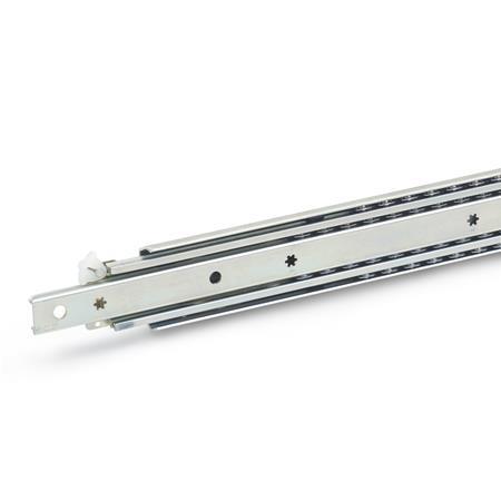
Telescopic slides GN 1426 are installed vertically and in pairs. The special design allows the stroke to achieve ≈ 100 % of the nominal length l1 on both sides (double-sided full extension). Applications such as the double-sided loading of a drawer can be realized in this way. The rubber stops of type B dampen the impact of the slide in the front end positions. If larger static or dynamic loads occur in the direction of extension, they should be absorbed by external stop elements.
The telescopic slides are delivered in pairs. They can be installed on the extension on either the left or right side due to the mechanics. All mounting holes are easy to reach through auxiliary holes. Only the fastening holes are shown, but other production-related holes may be present.
Specification
Slide profile
Steel, Zinc plated, blue passivatedZB
Bearings
Roller bearing steel, hardened
Ball cage
Steel, zinc plated
Rubber stop
Plastic / Elastomer
Operating temperature -20 °C to 100 °C
RoHS
On request
Other lengths and hole spacing
Other attachment options
Other surfaces
With support bracket


