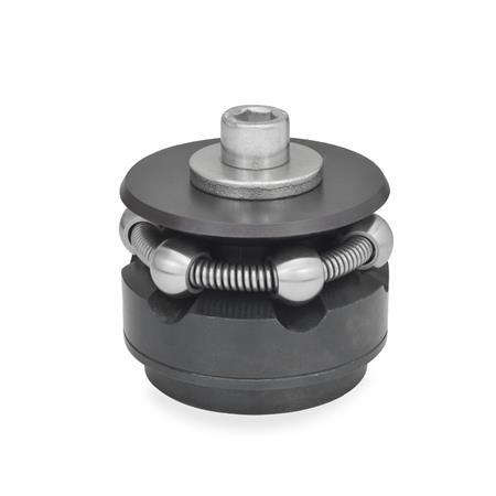
K | with clamping balls |
S | with clamping segments |
d1 | d2 Clamping-Ø | d3 | d4 | d5 | d6 | h1 | h2 | k ±0,1 | l1 | l2 | l3 | t min. | w1 | w2 | Number of clamping elements | Clamping force in kN |
---|---|---|---|---|---|---|---|---|---|---|---|---|---|---|---|---|
11,7* | 14,2 | 10 | M 4 | 4,3 | 1,5 | 3,5 | 2,5 | 3,5 | 3,9 | 8,6 | 6,3 | 4 | 0,7 | 1,3 | 3 | 0,5 |
14,5 | 18,5 | 12 | M 4 | 4,3 | 2 | 5,5 | 3,5 | 4,5 | 9,8 | 14,2 | 5 | 6 | 1,2 | 2,3 | 3 | 3,5 |
18,5 | 22,5 | 15 | M 5 | 5,3 | 2,5 | 7,5 | 3 | 5,5 | 11,5 | 16,5 | 6,2 | 7 | 1,2 | 2,3 | 3 | 4 |
22,5 | 26,5 | 20 | M 6 | 6,4 | 3 | 6 | 4 | 7 | 14,1 | 19,6 | 9 | 8 | 1,2 | 2,3 | 3 | 4,5 |
26,5 | 30,5 | 20 | M 6 | 6,4 | 3 | 6 | 4,5 | 7 | 14,1 | 19,8 | 9 | 8 | 1,2 | 2,3 | 3 | 4,5 |
30,5 | 38,5 | 25 | M 6 | 6,4 | 4 | 7 | 4,5 | 9 | 14,1 | 23,2 | 9 | 8 | 2,3 | 4,6 | 3 | 4,5 |
38,5 | 46,5 | 30 | M 8 | 8,4 | 4 | 7,5 | 4,5 | 11 | 18 | 27,2 | 12 | 10 | 2,3 | 4,6 | 6 | 6,5 |
46,5 | 54,5 | 30 | M 8 | 8,4 | 4 | 7,5 | 4,5 | 11 | 18 | 27,1 | 12 | 10 | 2,3 | 4,6 | 6 | 6,5 |
54,5 | 70,5 | 45 | M 10 | 10,5 | 5 | 9 | 5,5 | 15 | 23,7 | 40,6 | 14 | 12 | 4,7 | 9,2 | 6 | 8 |
70,5 | 86,5 | 60 | M 12 | 13 | 5 | 10 | 5,5 | 17 | 28,3 | 46,1 | 17 | 15 | 4,7 | 9,2 | 6 | 10 |
86,5 | 102,5 | 60 | M 16 | 17 | 5 | 10 | 5,5 | 25 | 30,3 | 51,2 | 21 | 15 | 4,7 | 9,2 | 6 | 12,5 |
A circular ball cage containing 3 or 6 balls is forced outwards over an accurately guided cone by means of a screw which, through the exerted thrust, will enlarge the outside diameter of the circular ball cage. This in turn will lead to a firm contact between the centering clamp and bore of the workpiece. Type K (with balls) is used for clamping applications where minor ball marks at the contact points with the workpiece are acceptable. Type S (with clamping segments) is used in such cases where marks at the clamping points on the workpiece would be acceptable. |
Our service team is available from Monday to Friday between 7:00 AM and 5:30 PM: +49 7723 6507 - 0