Product description
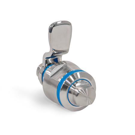
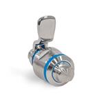
Latches GN 1150 are designed for use in hygienic areas and meet strict hygienic requirements (full hygiene) on the operating and latch arm side due to the special mounting nuts as well as the optimized latch arm and hexagon head screw. The locking mechanism is protected by multiple seals. At the same time, the high surface quality (Ra < 0.8 µm) and dead-space-free mounting prevent dirt from adhering and facilitate cleaning.
The latches create a secure closure by rotating a maximum of 90°, which positions the latch arm in the locked position behind the frame. Slanted surfaces on the latch arm ensure smooth positioning. Latch arms are available with different bend angles to cover a latch arm distance A from 22 to 44 mm.
The mounting holes in the housing must be at a right angle, free of burrs and without a chamfer. This ensures that the sealing rings will function properly.
Specification
Lock housing
Stainless steel AISI 316L
Latch arm
Stainless steel AISI 316
Seals
Blue, FDA-compliant
Temperature resistant -40 °C to +110 °C
- Sealing rings / O-ring
EPDME- Hardness 85 ±5 Shore A (Sealing rings)
- Hardness 70 ±5 Shore A (O-ring)
- Other seals / Wiper
TPU, hardness 95 ±5 Shore A
Other parts
Stainless steel AISI 316L
All moving parts
lubricated with FDA compliant special grease
Protection class IP 66
RoHS
Accessory
Sealing Rings GN 7600
Wipers GN 7607
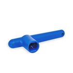
Socket Keys GN 1151
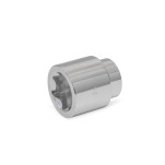
Sockets GN 3124

