Product description
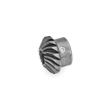
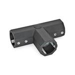
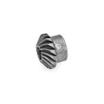
Bevel gear wheels GN 297 are used for angular / T-gears in connection with linear actuators / transfer units GN 391 and housings GN 298.
The spiral bevel facilitates both setting the desired clearance and locating the correct position of the bevel gears. Also, gears set up this way run with extremely low noise levels.
Two bevel gears are needed for an angular gear, three bevel gears are needed for a T-gear. These are available as set in type W resp. type T.
Please note that only bevel gears wheels with different pitches can be paired. The transmission ratio is always 1:1 because the bevel gears always have the same number of teeth.
Specification
Steel
Hardened
Teeth milled
RoHS

