Product description
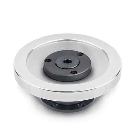
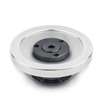
Safety handwheels GN 327 feature the ultimate in health and safety at work standards because the handwheel, if disengaged, is mounted on a fixed component, the bearing flange. The wheel is fully disengaged from the rotating shaft.
The bearing flange can also accept the bearing of the shaft via the bearing bushing (identification no. 1). This bearing bushing is a dry bearing (DU bushing). Normally, the shaft has a separate bearing and the bearing bushing serves to center the bearing flange.
Centering can also be effected by a centering ring (identification no. 2) if the appropriate bore hole has been made at the machine side. In this case there is no need for the bearing bushings and no bearing friction (heating) will occur.
Specification
Wheel body
Aluminum
- Hub machined
- Rim
- Turned on all sides
- Highly polished
Coupling elements
Steel
- Nitrided
- Bearing surface ground resp. PTFE-coated
- Bearing flange blackened
Revolving handle GN 598
Plastic, phenolic resin (PF)
- Black, shiny finish
- Spindle steel
Zinc plated, blue passivated
RoHS

