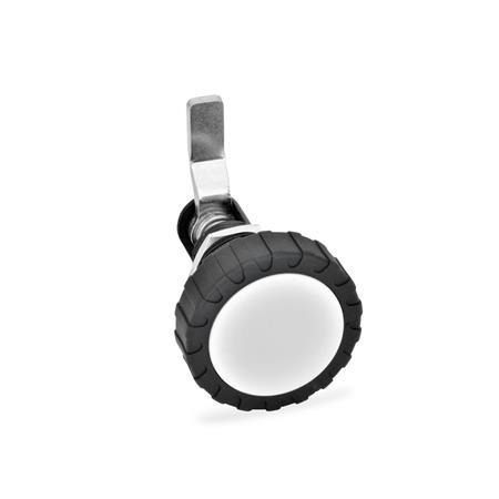
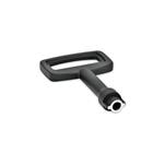
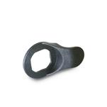
Product description
Rotary clamping latches GN 116.1 have a closing mechanism which transfers the rotary movement of the operating element or socket key into a 90° turn and then into a 12 mm (travel distance) axial movement of the latch arm. This configuration allows large closing strokes within the individual key spacings, e.g. in connection with seals.
Latch arms are available with different bend angles to cover a clamping range A1...A5 from 4 to 46 mm. The selected gradations ensure broad overlapping between the clamping ranges.
The permissible tightening torque for the clamping screw is 2 Nm, which brings the axial closing force of the latch arm to about 300 N.
Specification
Lock housing
Zinc die casting
Powder coated
Black, RAL 9006, textured finish
Other parts
Steel zinc plated, blue passivated
Knurled knob (Type RG)
Plastic (Polyamide PA)
- Handle black, matte finish
- Cover cap light gray, matte finish
RoHS

